
Page 8 - fero wirebond catalog
P. 8
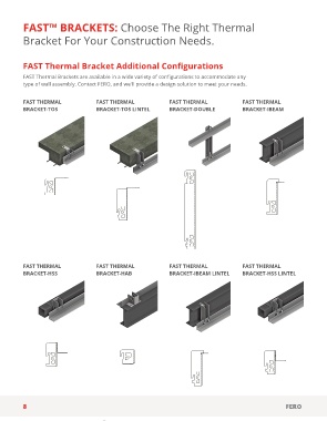
FAST™ BRACKETS: Choose The Right Thermal

        Bracket For Your Construction Needs.


        FAST Thermal Bracket Additional Configurations

        FAST Thermal Brackets are available in a wide variety of configurations to accommodate any
        type of wall assembly. Contact FERO, and we'll provide a design solution to meet your needs.

 Notes: 1. Design loads are the maximum allowable vertical loads that a FAST Thermal Bracket can support using its standard L4x4x1/4" (L102x102x6mm). Tests used a stiffened backing and
 shelf angle in order to isolate FAST Thermal Bracket capacities. Brackets were anchored using a 5/8” (16mm) bolt vertically centred in the bracket slot and a point load was applied 0.79” (20mm)
 o/c from the end (toe) of the angle. Tabled allowable loads are (unfactored) service loads, and have been established by test and calculation, and demonstrate a level of safety and performance   FAST THERMAL   FAST THERMAL    FAST THERMAL    FAST THERMAL
 consistent with North American design standards. Tabled allowable veneer heights are calculated as (maximum allowable vertical load per bracket) ÷ (weight of veneer per unit area x bracket   BRACKET-TOS  BRACKET-TOS LINTEL  BRACKET-DOUBLE  BRACKET-IBEAM
 spacing). 2. Anchor bolt slip resistance is higher than the stated design loads with proper FAST Thermal Bracket installation. Slots must be alternating and bolts should be tightened to snug
 plus half turn. 3. Veneer weights used are: 40lb/ft2 (195kg/m2) for clay brick; 30lb/ft2 (146kg/m2) for 105lb/ft3 (1682kg/m3) lightweight concrete block; 38lb/ft2 (185kg/m2) for 125lb/ft3 (2002kg/m3)
 normal weight concrete block; and 45.0lb/ft2 (220kg/m2) for natural stone. 4. The typical FAST Thermal Bracket slots are sized for a 5/8” (16mm) diameter anchor bolt, but brackets can be made
 for other anchor bolt diameters upon request. Comply with all manufacturer’s design and installation requirements pertaining to capacity, edge distances, torqueing etc. FERO does not assume
 responsibility for the design of the anchorage of the FAST Thermal Brackets. The values shown in this FAST System Load Table assume that the FAST Thermal Bracket is adequately anchored.
 5. Where the FAST™ system is designed/intended to support masonry veneer having panel height exceeding 30’ (9.1m), contact FERO for additional design information. 6. The bracket spacing may
 vary by ±4” (100mm). 7. Use the FERO Rectangular Washer when installing the FAST Thermal Bracket (required). 8. The FAST System Load Table applies to the FAST Standard, FAST Lintel, and FAST
 Inverted. This table will generally apply to the Extended FAST systems and custom FAST Thermal Brackets as well, but additional engineering may be required. Contact FERO for more information.
 9. FERO recommends not installing over gypsum sheathing (unless otherwise engineered) as tension from the anchor bolt may crush gypsum sheathing; unrelated to the FAST Thermal Brackets.


        FAST THERMAL                FAST THERMAL                FAST THERMAL                 FAST THERMAL
        BRACKET-HSS                 BRACKET-HAB                 BRACKET-IBEAM LINTEL         BRACKET-HSS LINTEL


        8                                                                                                    FERO


                                       D
     C                                                                                  C
                                                                C                          Manufacturing approval by:
                                                                                 Abbreviations   Approved by:  TM
                                                                           AT Angle Thickness
                                                                         C  D Depth        Material:   Size:  Dwg no:    Rev:
                                                                           H  Height
                                                                           MB  Mounting Bolt         C   Assembly2
                                                                           BT Bracket Thickness  Mass: N/A  Scale:  Autodesk inventor file  Sheet:  1  Of 1
                                                                           W Width
                                                1                     2                     3                     4
                Legal disclaimer:       Legal disclaimer:

                                                 FERO FAST™ Bracket
                                        THESE DRAWINGS ARE PROVIDED FOR INFORMATIONAL PURPOSES ONLY FOR DESIGN PROFESSIONALS. ALL RIGHTS   FERO FAST™ Bracket
                THESE DRAWINGS ARE PROVIDED FOR INFORMATIONAL PURPOSES ONLY FOR DESIGN PROFESSIONALS. ALL RIGHTS  RESERVED. ALL WORKS CONTAINED HEREIN ARE OWNED BY FERO CORPORATION AND PATENT PROTECTED.   United States Patent US 6,128,883
                RESERVED. ALL WORKS CONTAINED HEREIN ARE OWNED BY FERO CORPORATION AND PATENT PROTECTED.   United States Patent US 6,128,883
                MANUFACTURE IS NOT PERMITTED BY ANY PARTY OTHER THAN FERO CORPORATION. RECIPIENT OF THIS DRAWING  MANUFACTURE IS NOT PERMITTED BY ANY PARTY OTHER THAN FERO CORPORATION. RECIPIENT OF THIS DRAWING   Canadian Patents CA 2,284,069; CA 2,254,510; CA 2,591,687;
                ASSUMES ALL RISK AND LIABILITY FOR ANY LOSSES, DAMAGES, CLAIMS OR EXPENSES RESULTING FROM THE USE OF  ASSUMES ALL RISK AND LIABILITY FOR ANY LOSSES, DAMAGES, CLAIMS OR EXPENSES RESULTING FROM THE USE OF   CA 2,759,747; CA 2,759,837; and CA 2,759,778  Legal disclaimer:
                                           Canadian Patents CA 2,284,069; CA 2,254,510; CA 2,591,687;
                                        THESE DRAWINGS. THE AUTHOR OF THESE DRAWINGS IS NOT AN ARCHITECT OR ENGINEER.
                THESE DRAWINGS. THE AUTHOR OF THESE DRAWINGS IS NOT AN ARCHITECT OR ENGINEER.  CA 2,759,747; CA 2,759,837; and CA 2,759,778  Other Patents Pending
                                                 Other Patents Pending  Drawn by:                            THESE DRAWINGS ARE PROVIDED FOR INFORMATIONAL PURPOSES ONLY FOR DESIGN PROFESSIONALS. ALL RIGHTS

                                Drawn by:   2018-12-19  Copyright © 2018 FERO Corporation    Engineering  2018-12-19    ENGINEERED MASONRY CONNECTORS   RESERVED. ALL WORKS CONTAINED HEREIN ARE OWNED BY FERO CORPORATION AND PATENT PROTECTED.
                                Engineering
                                                                                                             MANUFACTURE IS NOT PERMITTED BY ANY PARTY OTHER THAN FERO CORPORATION. RECIPIENT OF THIS DRAWING
                                                        Checked by:
     D           Copyright © 2018 FERO Corporation  Checked by:  ENGINEERED MASONRY CONNECTORS   D  FERO  15305-117 Avenue NW,ENDOMONTON AB, CANADA T5M-3X4  D  ASSUMES ALL RISK AND LIABILITY FOR ANY LOSSES, DAMAGES, CLAIMS OR EXPENSES RESULTING FROM THE USE OF
                                            FERO
                                                                           Tel: (780) 455-5098 Fax: (780) 452-5969
                                                   15305-117 Avenue NW,ENDOMONTON AB, CANADA T5M-3X4
                                                   Tel: (780) 455-5098 Fax: (780) 452-5969  www.ferocorp.com  E-mail: info@ferocorp.com  THESE DRAWINGS. THE AUTHOR OF THESE DRAWINGS IS NOT AN ARCHITECT OR ENGINEER.
                                                   www.ferocorp.com  E-mail: info@ferocorp.com
                                         Title:         Manufacturing approval by:   Title:
                                Manufacturing approval by:   Approved by:  FERO FAST   System                 Copyright © 2018 FERO Corporation
                                                                           TM
                                         FERO FAST   System
                      Abbreviations   Approved by:  AT Angle Thickness  Abbreviations   TM  D
                AT Angle Thickness      D Depth                   Size:  Dwg no:      Rev:
                D Depth                 H  Height Dwg no:  Material:   Rev:
                                         Size:
                H  Height       Material:   MB  Mounting Bolt     C   Assembly2
                                          C
                                           Assembly2
                MB  Mounting Bolt       BT Bracket Thickness  Mass:  Scale:          Sheet:
                                         Scale:
                BT Bracket Thickness  Mass: N/A  W Width Autodesk inventor file  N/A  Sheet:  1  Of 1   Autodesk inventor file   1  Of 1   Abbreviations
                W Width
                                                                                                             D Depth
           2  1                  3  2                  4  3                     4                            AT Angle Thickness
                                                                                                             H  Height
                                                                                                             MB  Mounting Bolt
                                                                                                             BT Bracket Thickness
                                                                                                             W Width
                                                                                 1                      2